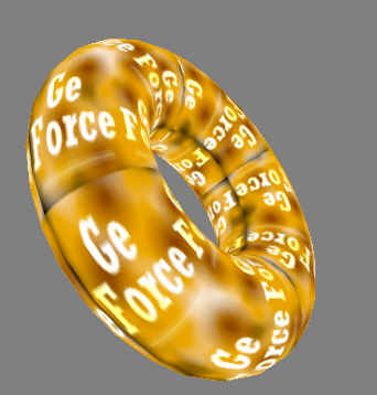
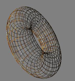
The texture with the phrase "OpenGL sets the standard" on it is wrapped around the surface of the torus (a fancy word for doughnut). We could just as easily applied a different texture image to give the torus a wood-grain appearance. The point is that we can map any flat image onto whatever geometry we want to render.
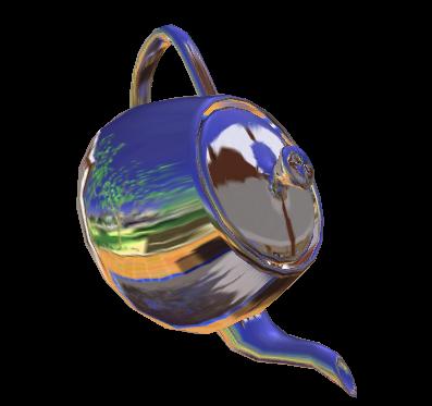
This conventional form of texture mapping is now wildly successfully. Nearly every 3D computer game today uses this form of texture mapping. Yet this conventional form of texture mapping is not well suited for all circumstances. Think of an object such as a silver candlestick. The shiny surface of the candlestick reflects the surroundings of the candlestick. Because the surface is reflective, there is not a single image that can be wallpapered onto the surface. If either the candlestick or the viewer position changes, the reflection in the candlestick changes. Instead of matching up candlestick vertices to fixed 2D locations on a flat texture image, reflective surfaces map locations on the object's surface to the appropriate reflected direction in the 360 degree environment surrounding the object.
Unfortunately the conventional approach to hardware texture mapping is not well suited to this problem. Instead of mapping a surface position to a location on a flat 2D texture image, we really want to map surface positions to directions in a 360 degree environment.
Look at the world around you. By just rotating your head and moving your eyes, you can look in a whole range of directions. Your environment can be thought of as an omni-directional image centered at your head. This is fundamentally different than looking up a location in a 2D image based on a 2D (x,y) position. If your environment could be encoded as a texture image, it would ideally be accessed via a 3D direction instead of a 2D position.
 back
back  bottom
 front
front  left
left
 right
right  top
top
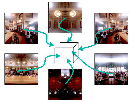
Here's a diagram showing how a different set of cube map images form the faces of a cube.
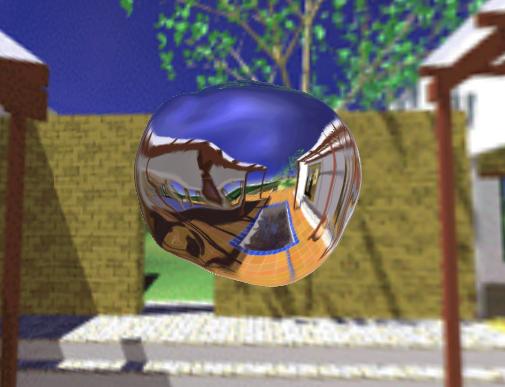
The actual program uses a physics model to distort the bubble's shape in real-time. The undulating bubble's surface results in a dynamic reflection of the patio environment.
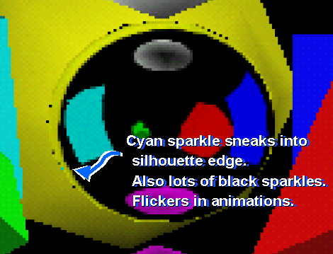
Cube mapping is just one way to implement environment mapping. Other approaches such as sphere mapping and dual paraboloid mapping (as developed by Heidrich & Seidel) can generate similar effects using only conventional texture mapping, but both techniques have serious drawbacks that limit their general use. Sphere mapping is simple and directly supported by OpenGL, but is view-dependent meaning that a different sphere map texture image is required for each different eye position. Additionally, sphere mapping is subject to unsightly "speckle" artifacts at the glancing edges of sphere mapped objects. The following image shows the speckle artifacts from sphere mapping:
Dual paraboloid mapping overcome these limitations, but is more expensive because it requires two texture units or two rendering passes. Dual paraboloid mapping also requires involved texture coordinate generation math (unless a special OpenGL texgen reflection extension is supported). Authoring texture images for either sphere maps or dual paraboloid maps is non-obvious because both require special image warping operations. Examples of the necessary warping for sphere and dual paraboloid maps is shown in the sample textures shown below:
 example sphere map
image
example sphere map
image
 front dual paraboloid
map
front dual paraboloid
map 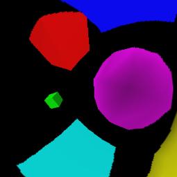 back dual
paraboloid map
back dual
paraboloid map
Cube map texturing is free from the artifacts of sphere mapping. Unlike dual paraboloid maps, cube maps require only a single texture unit and can be applied in a single rendering pass. Because the texture images for cube maps are merely the six cube faces of a cube environment, the cube map textures are easier to acquire from photographs or render dynamically. Cube maps also fully utilize the entire texture image resolution. Sphere and paraboloid maps uses only 78% of the actual texture resolution available in the texture map image than sphere or dual paraboloid maps which require extra warping steps.
Conceptually, cube map texturing is more straightforward than using the warped sphere map or dual paraboloid map approaches, but cube map texturing requires the special ability to access six texture images at once. This requires more sophisticated texturing hardware. While cube map texturing is more complex than conventional texture mapping, the rapid pace of semiconductor miniaturization has made single-chip implementations of hardware cube map texturing a reality today for consumer PCs. NVIDIA's GeForce 256 GPU is the first commercial consumer GPU to support cube map texturing.
Hardware is only useful if software interfaces are available to expose the hardware's capabilities. Fortunately in the case of texture cube mapping, both major Application Programming Interfaces (APIs) for 3D graphics now have support for cube map texturing. Microsoft's Direct3D API for Windows PCs supports cube map textures with its DirectX 7 update. OpenGL, the industry-standard API for Windows, Macs, Linux, and Unix workstations, now supports a multi-vendor EXT_texture_cube_map extension for cube map texturing. While support for cube map textures is new and only the newest hardware supports cube map texturing, software standards are in place today. NVIDIA's GeForce 256 supports both the DirectX 7 cube mapping and OpenGL EXT_texture_cube_map APIs today.
While cube maps are superior to the other approaches described, only state-of-the-art hardware supports cube map textures. The older sphere map and dual paraboloid methods for environment mapping may still be useful as a fallback when hardware cube map textures are not available. Cube map textures are more straightforward and efficient, but it good that techniques exist to support older hardware too.
One problem that plagues CAD programs is poor sampling of these specular highlights. The problem arises because CAD programs typically render 3D objects as solid meshes, yet only perform the expensive specular lighting computation at the mesh vertices. The lit colors computed at the mesh vertices are then interpolated across the mesh's surface. Unfortunately, if the mesh is not tight enough, specular highlights are poorly sampled. When rotating the object, this leads to "wobbly" specular highlights where the brightness of the highlight depends on how close it is to vertices within the mesh. The important specular visual cue is compromised. Making a tighter mesh is not always practical because the tighter the mesh, the more expensive and slower it is to render the object. Ideally, specular highlights should be bright and stable without worrying about the density of the object's vertex mesh.
Cube maps provide a straightforward means to render stable specular highlights. Multiple specular highlights can be encoded in a cube map texture. This cube map texture can then be accessed based on the surface's reflection vector. Instead of computing the color per-vertex and interpolating the color across the surface, the hardware only computes the reflection vector (cheaper than computing the actual specular lighting contribution) and interpolates this vector to supply cube map texture coordinates. The result is bright, stable specular highlight and a truer sense of surface curvature. Below is an example using cube map textures for stable specular highlights. The image on the left uses a cube map texture and the white and orange specular highlights are clearly visible. The image on the right uses conventional per-vertex lighting; its specular highlights are murky in the static image below and wobble when the model is rotated interactively.
![]()
Cube maps are a better alternative to massive over-tesselation of models to achieve stable specular highlights. Another advantage of using cube map textures to generate stable specular highlights is that the number of specular light sources (all encoded in a single cube map texture) is independent of the rendering performance. Additional specular highlights can be encoded in a single cube map texture map (in advance of interactive rendering) with no additional interactive rendering overhead.
The one limitation of this approach is that the specular light sources must be either distant or infinite lights for this scheme to work well. Fortunately, CAD programs often use infinite light sources.
A cube map can capture the diffuse contribution from skylight illumination. Accessing the cube map based on the surface normal vector (as opposed to the reflection vector used for stable highlights and environment maps) can provide a quick estimate of the diffuse illumination from the skylight. Computing a cube map for a particular skylight configuration is complex, but several computer graphics researchers have devoted considerable effort to modeling reasonable skylight illumination.
See the SIGGRAPH '99 paper "A Practical Analytic Model for Daylight" by Preetham, Shirley, and Smits. Other valuable references include Klassen's "Modeling the Effect of the Atmosphere on Light" (ACM Transactions on Graphics, July 1987) and Tadamura, et.al.'s "Modeling of Skylight and Rendering of Outdoor Scenes" (EUROGRAPHICS '93).
Dynamic cube map environment mapping does exactly that. A dynamic cube map texture is generated by first render the scene six times from the point of view of the reflective object. Each view is a different orthogonal 90 degree view frustum corresponding to one of the six faces of the cube map. In OpenGL, you can use the glCopySubTexImage2D surfac- positions to directions in a 360 degree environment. command to copy each rendered cube face into the cube map. Once the dynamic environment has been rendered and copied into the face of the cube map texture, render the scene normally using the dynamic cube map texture when rendering the reflective object.
As you would expect, this is significantly more expensive than static cube map environment mapping because of all the extra rendering steps. It can still be done at interactive rates though. The following image was generated by a program called "guts" that implements dynamic cube map reflections:
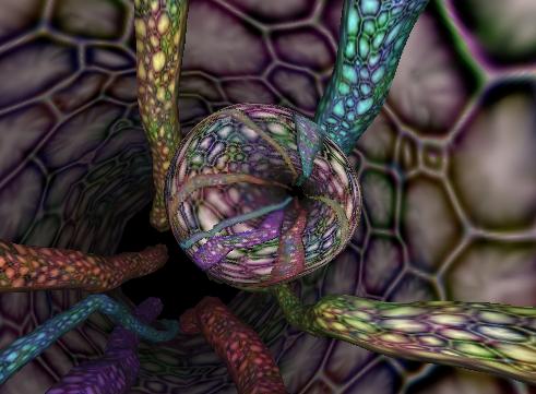
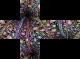
In the guts program, the deforming bubble is now floating through a virtual intestinal tract (yummy, huh). As the bubble moves through the tract, the bubble constantly reflects the walls and features of the intestines. The image below shows the dynamically rendered faces of the cube map texture:
This technique gets even more expensive if there are multiple reflective objects in the scene. Each reflective object typically requires its own unique dynamic environment map. And if reflective objects can reflect the reflections of other reflective objects, things get even more complicated. It is actually possible to generate recursively a set of dynamic cube maps of reflective objects reflecting each other. This approach can approximate some of the effects usually generated using ray tracing algorithms.
Just to demonstrate that this recursive approach is possible, the image below shows two reflective spheres. Look carefully and you will see that the lower sphere contains the reflection of the upper sphere! More recursions of dynamic cube mapping could generate the reflection of the lower sphere in the upper sphere, but since the image below takes 18 rendering passes to generate cube faces, already the algorithm is impractical for interactive use.
The previously discussed environment mapping, stable specular highlights, and skylight illumination applications for cube maps are arguably just special cases of more general per-pixel lighting techniques. Because lighting computations rely so heavily on 3D direction vectors, cube maps that are accessed via direction vectors are natural for expressing per-pixel lighting operations.
State-of-the-art per-pixel lighting requires hardware support for per-pixel operations such as dot products and complex blending of texture results. The details of this are beyond the scope of this tutorial. The discussion here serves only to hint at how cube maps can be used in conjunction with advanced texture environment functionality. A cube map can be used to normalize vectors that are computed per-vertex and then interpolated across a polygon's interior. Lighting computations often require normalized vectors to operate correctly. A cube map can also be used to compute more complex functions. The half-angle vector used for Blinn-style specular highlights is the normalization of the view and light vectors. For a constant light vector (to a distant or infinite light), a cube map can generate the normalized half-angle given a varying view vector.
Here are a few examples of what is possible. All of these images were generated from OpenGL programs that run in real-time using a GeForce 256 GPU. This first example shows a single polygon. A normal map texture supplies a wavy pattern to the surface. A cube map texture is used to compute the half-angle assuming a varying view vector. The directional light (indicated in yellow) supplies specular, diffuse, and ambient light contributions that are all computed per-pixel using a single multitextured rendering pass.
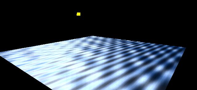
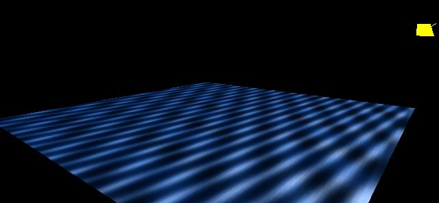
This second image demonstrates how only changing the light position results in a substantially different surface appearance. No texture image data was changed between the two images. Notice how the first image shows bright specular highlights across the polygon. These highlights are not visible in the second image due to the changed light position.
Ultimately, cube map-based per-pixel lighting techniques will result in startlingly complex surface appearances displayed at real-time rates. Below is an example that uses three GeForce 256 rendering passes to model ambient, diffuse, and specular lighting contributions based on per-pixel perturbed normals and a separate per-pixel surface decal texture. The cube map texture is used to normalize per-pixel the light vector and half-angle vectors that are computed per-vertex by GeForce's hardware Transform & Lighting engine. The two images shown use different normal perturbation maps and differing light directions:
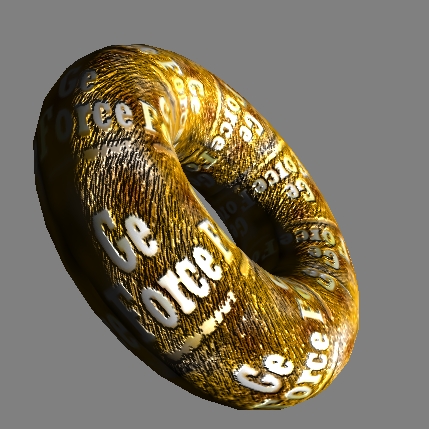
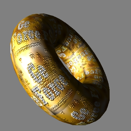
Comparing these two images to the first torus image in this tutorial shows the huge difference per-pixel lighting techniques can make in the appearance of computer-rendered objects. Also notice the specular highlights in both images. The wire frame image below shows the tessellation of the torus. Notice how the per-pixel detail far exceeds the tessellation of the base torus geometry.
The OpenGL cube map extension is named EXT_texture_cube_map. The EXT prefix means that the extension is a multi-vendor extension. SGI and NVIDIA sponsored the texture cube map extension.
For cube map textures, there is a new texture target GL_TEXTURE_CUBE_MAP_EXT enumerant (the EXT suffix just indicates that the enumerant is for an EXT extension; all the new cube map enumerants have this suffix). This is the enumerant that you should pass to glBindTexture, glTexParameter, glEnable, and glDisable when using cube map textures.
But the GL_TEXTURE_CUBE_MAP_EXT enumerant is not used for glTexImage2D and related commands such as glCopySubTexImage2D. The texture cube map extension makes a distinction not necessary for the other texture targets. While 1D, 2D, and 3D textures have only a single set of image mipmap levels, every cube map texture has six distinct sets of image mipmap levels. Each texture target can be mipmapped so the complete image for 1D, 2D, and 3D textures is really a set of mipmap levels. For cube maps textures, each cube map face has its own set of mipmap levels. Because cube maps have six faces (the other texture types can be thought of as having only one face each), the texture cube map extension makes a distinction between the cube map "texture as a whole" target and the six "texture image" targets. The six cube map texture image targets are:
GL_TEXTURE_CUBE_MAP_POSITIVE_X_EXTThese targets correspond to the six cube map faces. If you think of a cube map texture as centered at the origin of and aligned to an XYZ coordinate system, each face is named by the positive or negative X, Y, or Z axis that pierces its face.
GL_TEXTURE_CUBE_MAP_NEGATIVE_X_EXT
GL_TEXTURE_CUBE_MAP_POSITIVE_Y_EXT
GL_TEXTURE_CUBE_MAP_NEGATIVE_Y_EXT
GL_TEXTURE_CUBE_MAP_POSITIVE_Z_EXT
GL_TEXTURE_CUBE_MAP_NEGATIVE_Z_EXT
One convenient thing about the cube map "texture image" targets is that the enumerants are laid out in sequential order so that
GL_TEXTURE_CUBE_MAP_POSITIVE_Y_EXT = GL_TEXTURE_CUBE_MAP_POSITIVE_X_EXT + 2,These cube map "texture image" targets are the enumerants that should be used with glTexImage2D, glCopyTexImage2D, glTexSubImage2D, glCopySubTexImage2D, glGetTexImage, and glGetTexLevelParameter to update or query the specified image of the "texture image" target's respective cube map face.
GL_TEXTURE_CUBE_MAP_NEGATIVE_Z_EXT = GL_TEXTURE_CUBE_MAP_POSITIVE_X_EXT + 5, etc.
Cube map images must always have square dimensions so the faces can form a cube. In addition to the other texture consistency rules specified by OpenGL, all the faces at a given level of a cube map must have the same dimensions and the width and height of each particular image in the cube map must be equal.
Like the other texture targets, cube map textures support a special "proxy" target used to query if a given texture target configuration is supported by the OpenGL implementation. The cube map texture proxy target is GL_PROXY_TEXTURE_CUBE_MAP_EXT. Because you never actually use the proxy target for texturing, instead you only query if it works or not, and because all the dimensions of all the faces for a given level of any cube map must have identical dimensions, there are not six proxy texture targets for each cube map face. A single cube map proxy target suffices.
For consistency with how the 3D texture target was added, there is also a new implementation defined constant GL_MAX_CUBE_MAP_TEXTURE_SIZE_EXT that indicates the maximum cube map texture size supported by the OpenGL implementation. In practice, the proxy mechanism is a preferable means to determine the implementation's specific limits.
GLubyte face[6][64][64][3];Each face in the example above is a 64x64 RGB image.for (i=0; i<6; i++) {
glTexImage2D(GL_TEXTURE_CUBE_MAP_POSITIVE_X_EXT + i,
0, //level
GL_RGB8, //internal format
64, //width
64, //height
0, //border
GL_RGB, //format
GL_UNSIGNED_BYTE, //type
&face[i][0][0][0]); // pixel data
}
Establishing mipmaps is not any more difficult. You can use the gluBuild2DMipmaps routine for establishing mipmap textures for cube map faces just like 2D textures. Instead of passing GL_TEXTURE_2D for the target parameter, pass in one of the "texture image" cube map targets. Example:
gluBuild2DMipmaps(GL_TEXTURE_CUBE_MAP_NEGATIVE_X_EXT,
GL_RGB8, 64, 64, GL_RGB, GL_UNSIGNED_BYTE, &face[1][0][0][0]);
glEnable(GL_TEXTURE_CUBE_MAP_EXT);As stated earlier remember that for a cube map texture to be consistent, all the faces of all required levels must be square and have the same dimensions (in addition to the standard OpenGL texture consistency rules). If the texture is not consistent, OpenGL is required to act as if the inconsistent texture unit is disabled.
glDisable(GL_TEXTURE_CUBE_MAP_EXT);
OpenGL has a priority scheme when multiple texture targets are enabled at the same time. Cube map texturing occurs when cube map texturing is enabled even if 3D, 2D, or 1D texturing is also enabled. The texturing enable priority is cube map, 3D, 2D, and finally 1D.
For cube map texturing, the (s,t,r) texture coordinates are treated as a direction vector (rx,ry,rz) emanating from the center of a cube. (The q coordinate can be ignored since it merely scales the vector without affecting the direction.) At texture application time, the interpolated per-fragment (s,t,r) selects one of the cube map face's 2D mipmap sets based on the largest magnitude coordinate direction (the major axis direction). The target column in the table below explains how the major axis direction maps to the 2D image of a particular cube map target.
major axisUsing the sc, tc, and ma determined by the major axis direction as specified in the table above, an updated (s,t) is calculated as follows
direction target sc tc ma
---------- --------------------------------- --- --- ---
+rx GL_TEXTURE_CUBE_MAP_POSITIVE_X_EXT -rz -ry rx
-rx GL_TEXTURE_CUBE_MAP_NEGATIVE_X_EXT +rz -ry rx
+ry GL_TEXTURE_CUBE_MAP_POSITIVE_Y_EXT +rx +rz ry
-ry GL_TEXTURE_CUBE_MAP_NEGATIVE_Y_EXT +rx -rz ry
+rz GL_TEXTURE_CUBE_MAP_POSITIVE_Z_EXT +rx -ry rz
-rz GL_TEXTURE_CUBE_MAP_NEGATIVE_Z_EXT -rx -ry rz
s = ( sc/|ma| + 1 ) / 2If |ma| is zero or very nearly zero, the results of the above two equations need not be defined (though the result may not lead to GL interruption or termination). Once the cube map face's 2D mipmap set and (s,t) is determined, texture fetching and filtering proceeds like standard OpenGL 2D texturing.
t = ( tc/|ma| + 1 ) / 2
glTexCoord3f(s,t,r); // user-supplied direction vector for cube map texturingIn practice however, it usually makes more sense to use one of OpenGL's texture coordinate generation modes. Two new texgen modes are added that generate the eye-space reflection vector or normal vector in the (s,t,r) texture coordinates. Reflection map example:
glVertex3f(x,y,z);
glTexGenfv(GL_S, GL_TEXTURE_GEN_MODE, GL_REFLECTION_MAP_EXT);Normal map example:
glTexGenfv(GL_T, GL_TEXTURE_GEN_MODE, GL_REFLECTION_MAP_EXT);
glTexGenfv(GL_R, GL_TEXTURE_GEN_MODE, GL_REFLECTION_MAP_EXT);
glEnable(GL_TEXTURE_GEN_S);
glEnable(GL_TEXTURE_GEN_T);
glEnable(GL_TEXTURE_GEN_R);
glTexGenfv(GL_S, GL_TEXTURE_GEN_MODE, GL_NORMAL_MAP_EXT);For these two modes to operate correctly, correct per-vertex normals must be supplied.
glTexGenfv(GL_T, GL_TEXTURE_GEN_MODE, GL_NORMAL_MAP_EXT);
glTexGenfv(GL_R, GL_TEXTURE_GEN_MODE, GL_NORMAL_MAP_EXT);
glEnable(GL_TEXTURE_GEN_S);
glEnable(GL_TEXTURE_GEN_T);
glEnable(GL_TEXTURE_GEN_R);
These new GL_REFLECTION_MAP_EXT and GL_NORMAL_MAP_EXT enumerants share the same respective values and functionality as the GL_REFLECTION_MAP_NV and GL_NORMAL_MAP_NV enumerants provided by the NV_texgen_reflection extension (this is extension is typically used in the absence of cube maps to implement a dual paraboloid map scheme).
The GL_EYE_LINEAR texgen mode is also useful with cube maps as a way of generating the unnormalized view vector.
OpenGL's texture matrix is also very useful for manipulating cube map texture coordinates. The texture matrix can be used to rotate an (s,t,r) vector from one space to another. For example, if your cube map texture is oriented in world coordinate space, and M is the matrix transform that moves from world coordinates to eye coordinates, you can load the inverse of the affine portion of M into the texture matrix to rotate the eye-space reflection or normal vectors generated by GL_REFLECTION_MAP_EXT or GL_NORMAL_MAP_EXT back into world space.
If you do not find that the texture cube map extension is supported, it may be possible to use sphere mapping or dual paraboloid mapping as a substitute for cube map texturing
There are no new entry points for cube map texturing. Windows OpenGL programmers do not have to worry about using wglGetProcAddress to use the texture cube map extension. Instead, the existing 2D texture commands are used for cube maps too. The only addition to the OpenGL API required for the texture cube map extension is a new set of cube map enumerants. In case your version of OpenGL's <GL/gl.h> header file does not include the new enumerants for the EXT_texture_cube_map extension, consider placing the following in a header file of your own:
#include <GL/gl.h>
#ifndef GL_EXT_texture_cube_map
/* EXT_texture_cube_map */
#define GL_EXT_texture_cube_map 1
#define GL_NORMAL_MAP_EXT 0x8511
#define GL_REFLECTION_MAP_EXT 0x8512
#define GL_TEXTURE_CUBE_MAP_EXT 0x8513
#define GL_TEXTURE_BINDING_CUBE_MAP_EXT 0x8514
#define GL_TEXTURE_CUBE_MAP_POSITIVE_X_EXT 0x8515
#define GL_TEXTURE_CUBE_MAP_NEGATIVE_X_EXT 0x8516
#define GL_TEXTURE_CUBE_MAP_POSITIVE_Y_EXT 0x8517
#define GL_TEXTURE_CUBE_MAP_NEGATIVE_Y_EXT 0x8518
#define GL_TEXTURE_CUBE_MAP_POSITIVE_Z_EXT 0x8519
#define GL_TEXTURE_CUBE_MAP_NEGATIVE_Z_EXT 0x851A
#define GL_PROXY_TEXTURE_CUBE_MAP_EXT 0x851B
#define GL_MAX_CUBE_MAP_TEXTURE_SIZE_EXT 0x851C
#endif
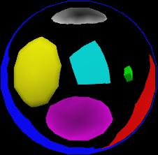
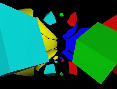
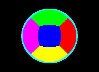
The cubemap.c example is a very basic program. It creates a cube map where every cube map face is a different solid color. Then the example draws a sphere with GL_REFLECTION_MAP_EXT texgen. The result should look like this:
The cm_demo.c example is a bit more interesting. The outdoor patio environment is loaded into a cube map and use to environment map a teapot, torus, or sphere. You can spin the object and see how the reflection changes. You can also switch between reflection mapping or normal mapping. Additionally, if you OpenGL implementation also supports the EXT_texture_lod_bias extension, you can switch between a shiny or dull environment map. Here's a snapshot: